Pesquisar neste blog

19/03/2020

Variável em CCS C Compiler


Código feito em CCS C Compiler

#include <main.h>
#use delay(clock = 20MHz)

int x;

void main(){

    while(true){
      output_high(PIN_B2);
      delay_ms(1000);
      output_low(PIN_B2);
      delay_ms(1000);
   
      x++;//cada piscada soma +1
      if(x == 5){
         output_high(pin_b7);
               
      }
   }

}

18/03/2020

LCD com PIC 16F877A

Impressão no LCD com PIC 16F877A


Código feito em CCS C Compiler

#include <lcd1.h>
#include <KBD.C>
#include <lcd.c>

void main(){

   kbd_init();
   lcd_init();

   while(TRUE){
      printf(lcd_putc,"\fOla Mundo");
      delay_ms(1000);
   }

}

17/03/2020

Desafio 5 LCD

Desafio: Escrever caractere manualmente de acordo com a tabela ASCII
LCD manual


Controle em inglês


Controle em português


Tabela ASCII


Exemplo: Escrever FBD

Passo 1:
0000 1111 => Visor ligado (ligar o visor e ficar piscando)

Passo 2:
Habilita e desabilita o enable E

Passo 3:
0011 1000 => 2 Linhas do LCD (define 2 linhas )

Passo 4:
Habilita e desabilita o enable E

Passo 5:
F = 0100 0110

Passo 6:
Habilita RS

Passo 7:
Habilita e desabilita o Enable

Passo 8:
B = 0100 0010

Passo 9:
Habilita RS

Passo 10:
Habilita e desabilita o Enable

Passo 11:
D = 0100 0110

Passo 12:
Habilita RS

Passo 13:
Habilita e desabilita o Enable


Palavras chave:

כתוב תו ידני לפי טבלת ASCII
Tulis karakter kanthi manual miturut tabel ASCII
Persona scribam tincidunt ASCII ad mensam
Psát znak ručně podle tabulky ASCII
Skriv tegn manuelt i henhold til ASCII-tabellen
根據ASCII表手動寫入字符
Kọ kikọ silẹ pẹlu ọwọ ni ibamu si tabili ASCII
Skriv tecken manuellt enligt ASCII-tabellen
Γράψτε τον χαρακτήρα χειροκίνητα σύμφωνα με τον πίνακα ASCII
अक्षर ASCII तालिका अनुसार म्यानुअली लेख्नुहोस्
Skriuw karakter manuell neffens de ASCII-tabel
Isulat sa sulud ang karakter nga sumala sa lamesa sa ASCII

16/03/2020

Display hexadecimal de 7 segmentos

Display hexadecimal de 7 segmentos usando microntrolador PIC 16F877A


Código feito em CCS C Compiler

#include <16f877a.h>
#use delay(crystal = 20MHz)

void main(){
   while(true){
      output_b(0b00111111);//0
      delay_ms(500);//espera 0.5 s
   
      output_b( 0b00000110);//1
      delay_ms(500);
   
      output_b(0b01011011);
      delay_ms(500);
   
      output_b(0b01001111);
      delay_ms(500);
   
      output_b(0b1100110);
      delay_ms(500);
   
      output_b(0b01101101);
      delay_ms(500);
   
      output_b(0b00000111);//6
      delay_ms(500);
   
      output_b(0b01111111);
      delay_ms(500);
   
      output_b(0b1100111);//9
      delay_ms(500);
   
      output_b(0b1110111);//A
      delay_ms(500);
   
      output_b(0b1111100);//B
      delay_ms(500);
   
      output_b(0b0111001);//c
      delay_ms(500);
   
      output_b(0b1011110);//D
      delay_ms(500);
   
      output_b(0b1111001);//E
      delay_ms(500);
   
      output_b(0b1110001);//f
      delay_ms(500);
   
   
   }
}
 

Palavras chave:

תצוגה הקסדצימאלית בת 7 קטעים באמצעות בקר מיקרו PIC16F877A
ຈໍສະແດງຜົນ hexadecimal 7 ສ່ວນໂດຍໃຊ້ PIC16F877A microcontroller
7-segmentni šestnajstiški prikaz z uporabo mikrokrmilnika PIC16F877A
Hiển thị thập lục phân 7 đoạn bằng vi điều khiển PIC16F877A
7-segment hexadecimal kuratidza uchishandisa PIC16F877A microcontroller
7-сегментний шестидесятковий дисплей за допомогою мікроконтролера PIC16F877A
PIC16F877A മൈക്രോകൺട്രോളർ ഉപയോഗിച്ച് 7-സെഗ്മെന്റ് ഹെക്സാഡെസിമൽ ഡിസ്പ്ലേ

15/03/2020

Botao com Led usando PIC 16F877A

Faça um programa que utilize 2 botoes, um botão terá a função de ligar um led. O outro botão, quando pressionado irá deligar o led.


Código feito em CCS C Compiler

#include <16f877a.h>
#use delay(crystal = 20MHz)

void main(){
   while(true){
 
      if( input(pin_b0) == 1){//se precionado o botão1
         output_high(pin_b7);//liga o led
      }
   
      if( input(pin_b6) == 1){//se precionado o botao2
         output_low(pin_b7);//desliga o led2
      }
   }
}

13/03/2020

Contador crescente e decrescente usando PIC

Contador hexadecimal crescente e decrescente usando PIC 16F877A


Código feito em CCS C Compiler

#include <16f877a.h>
#use delay(crystal = 20 MHz)

void main(){
   char value[] = {0b0111111, 0b0000110, 0b1011011, 0b1001111, 0b1100110, 0b1101101, 0b1111101, 0b0000111,
   0b11111111, 0b1100111, 0b1110111, 0b1111100, 0b0111001, 0b1011110, 0b1111001, 0b1110001};
 
   while(true){
      for(int i = 0; i <=15; i++){
         output_b(value[i]);
         delay_ms(500);
      }
     
      for(i = 16; i >=1; i--){
         output_b(value[i-1]);
         delay_ms(500);
      }
   }

Desafio 2

Ligar e desligar um led através de um push booton


Código1 feito em CCS C Compiler

#include <16F877A.h>
#use delay(crystal = 20 MHz)

void main(){
   while(true){
      if(input(pin_b0) == 1){
         output_high(pin_b7);
      }
   
      if(input(pin_b0) == 0){
         output_low(pin_b7);
      }
   }
}
 
Código2 feito em CCS C Compiler

#include <16F877A.h>
#use delay(crystal = 20 MHz)

void main(){
   while(true){
      if(input(pin_b0) == 1){
         output_high(pin_b7);
       
      }else{// senao desliga o led
         output_low(pin_b7);
      }
   }
}

12/03/2020

Sequencia de leds1

Ligando uma sequencia de leds com apenas uma porta no PIC 16F877A


Código1 feito em CCS C Compiler

#include <16f877a.h>
#use delay(crystal = 20MHz)

void main(){
   while(true){
      output_b(0b11111111);//b7,b6,b5... b0 ligando todas as potas
     
   }
}

Código2 feito em CCS C Compiler

#include <16f877a.h>
#use delay(crystal = 20MHz)

void main(){
   while(true){
      output_b(0b11010101);//b7,b6,b5... b0 ligando todas as potas
     
   }
}

Código3 feito em CCS C Compiler

#include <16f877a.h>
#use delay(crystal = 20MHz)

void main(){
   while(true){
      output_b(153);//b7,b6,b5... b0 ligando todas as potas
     
   }
}

Código4 feito em CCS C Compiler


#include <16f877a.h>
#use delay(crystal = 20MHz)

void main(){
   while(true){
      output_b(255);//b7,b6,b5... b0 ligando todas as potas
      delay_ms(500);//desliga por 0,5 s
      output_b(10);//liga a porta rb3 e rb 1
      delay_ms(500);//espera 0,5s
      output_b(20);
      delay_ms(500);
      output_low(pin_b6);//desliga o pino b6
     
   }
}

11/03/2020

Semáforo usando PIC 16F877A


Código feito em CCS C Compiler

#include <16f877a.h>
#use delay(crystal=20MHz)

void main(){
   while(true){

      //output_high(pin_b2);//ligando o led verde

      output_high(pin_b0);//ligando o vermelho
      output_low(pin_b1);//desligando o amarelo
      output_low(pin_b2);//desligando o verde
      delay_ms(3000);//espera 3s
   
      output_low(pin_b0);
      output_high(pin_b2);
      delay_ms(2000);

      output_low(pin_b2);//desliga o led vermelho
      output_high(pin_b1);// e liga o led amarelo
      delay_ms(1500);//espera 1,5s
      output_low(pin_b1);// e espera o led amarelo

   }
}

26/02/2020

Push boton com PIC 16F877A

Objetivo: Inverter o estado do Led a cada vez que for pressionado


Código feito em CCS C Compiler

#include <16f877a.h>
#use delay(crystal=20MHz)

void main(){
 
   while(true){
      if(input(pin_b0) == 1){
         output_toggle(pin_b1);//troca o estado do led
         delay_ms(500);// e espera 0,5s
      }
   }

}

Pisca Leds 4 com PIC 16F877A


Código feito em CCS C Compiler:

#include <16f877a.h>
#use delay(crystal=20MHz)

void main(){
   char value[]={0b00000001, 0b00000011, 0b00000110, 0b00001100, 0b00011000, 0b00010000};
 
   while(true){
   
      for(int i=0; i<= 5; i++){
         output_b(value[i]);
         delay_ms(500);
      }
   
      for(i=6; i>= 1; i--){
         output_b(value[i-1]);
         delay_ms(500);
      }
   
   }
}

25/02/2020

Display 7 segmentos usando PIC 16F877A (3)


Código feito em mikro PRO for

void main() {
     trisb = 0; //definindo todos os pinos como porta de saída
     portb = 0; //desligando todos os pinos
   
     while(1){  //tudo que estiver aqui dentro irá repetir infinitamente
          portb = 0b00111111;//forma binária, 'imprimndo o [0]'
          delay_ms(500);

          portb = 0b00000110;//'imprimndo o [1]'
          delay_ms(500);

          portb = 91; //forma decimal, 'imprimindo o [2]'
          delay_ms(500);

          portb = 79;  // [3]
          delay_ms(500);//0,5s de espera

          portb = 0x66; //forma hexadecimal [4]
          delay_ms(500);

          portb = 0x6D; //forma hexadecimal  [5]
          delay_ms(500);

          portb = 0x7D; // [6]
          delay_ms(500);

          portb = 0x7;// forma hexadecimal  [7]
          delay_ms(500);

          portb = 0b01111111;//[8]
          delay_ms(500);

          portb = 0b01100111; //[9]
          delay_ms(500);
     }
}

24/02/2020

Display 7 segmentos com PIC 16F877A (2)

Laço de repetição no display de 7 segmentos usando goto


Código feito em mikro PRO for

void main() {

      trisb = 0;//definindo todos os pinos como saída
      portb = 0; //desligando

      inicio:
      portb = 0b00111111;//forma binária, 'imprimndo o [0]'
      delay_ms(500);

      portb = 0b00000110;//'imprimndo o [1]'
      delay_ms(500);

      portb = 91; //forma decimal, 'imprimindo o [2]'
      delay_ms(500);

      portb = 79;  // [3]
      delay_ms(500);//0,5s de espera

      portb = 0x66; //forma hexadecimal [4]
      delay_ms(500);

      portb = 0x6D; //forma hexadecimal  [5]
      delay_ms(500);

      portb = 0x7D; // [6]
      delay_ms(500);

      portb = 0x7;// forma hexadecimal  [7]
      delay_ms(500);

      portb = 0b01111111;//[8]
      delay_ms(500);

      portb = 0b01100111; //[9]
      delay_ms(500);
      goto inicio;  //retorna para para o inicio
}

Desafio 1

Fazer o Led piscar conforme o gráfico


Resolução:

Código feito em CCS C Compiler

#include <16F877A.h>
#device adc=8

#FUSES NOWDT                    //No Watch Dog Timer
#FUSES HS                       //High speed Osc (> 4mhz for PCM/PCH) (>10mhz for PCD)
#FUSES NOPUT                    //No Power Up Timer
#FUSES NOPROTECT                //Code not protected from reading
#FUSES NODEBUG                  //No Debug mode for ICD
#FUSES BROWNOUT                 //Reset when brownout detected
#FUSES NOLVP                    //No low voltage prgming, B3(PIC16) or B5(PIC18) used for I/O
#FUSES NOCPD                    //No EE protection
#FUSES NOWRT                    //Program memory not write protected

#use delay(clock=20000000)

void main(){

   while(TRUE){
      output_low(PIN_B2);
   
      for(int i = 0; i< 50; i++){
         for(int j = 0; j < 100; j++){
            output_high(PIN_B2);
            delay_us(i*(1000/50));
            output_low(PIN_B2);
            delay_us(1000-(1*(1000/50)));
         }
      }
   }

}


18/02/2020

Pisca Leds 3 com PIC 16F877A

Objetivo: Piscar leds consequentemente usando for


Código feito em CCS C Compiler

#include <16F877a.h>
#use delay(crystal=20MHz)

void main(){
   char pins[] = {PIN_B0,PIN_B1,PIN_B2,PIN_B3,PIN_B4};
 
   while(TRUE){
      for(int i=0; i<=4; i++){
         output_high(pins[i]);
         delay_ms(250);
         output_low(250);
         delay_ms(250);
      }
   
      for(i=5; i>=1; i--){
         output_high(pins[i-1]);
         delay_ms(250);
         output_low(pins[i-1]);
         delay_ms(250);
      }
   }
}

Display 7 segmentos usando PIC 16F877A (1)


Código feito em mikro PRO for

void main() {
      trisb = 0;//definindo todos os pinos como saída
      portb = 0; //desligando
   
      portb = 0b00111111;//forma binária, 'imprimndo o [0]'
      delay_ms(500);
   
      portb = 0b00000110;//'imprimndo o [1]'
      delay_ms(500);
   
      portb = 91; //forma decimal, 'imprimindo o [2]'
      delay_ms(500);
   
      portb = 79;  // [3]
      delay_ms(500);//0,5s de espera
   
      portb = 0x66; //forma hexadecimal [4]
      delay_ms(500);
   
      portb = 0x6D; //forma hexadecimal  [5]
      delay_ms(500);
   
      portb = 0x7D; // [6]
      delay_ms(500);
   
      portb = 0x7;// forma hexadecimal  [7]
      delay_ms(500);
   
      portb = 0b01111111;//[8]
      delay_ms(500);
   
      portb = 0b01100111; //[9]
      delay_ms(500);
}

PiscaLed 2 com PIC 16F877A

Objetivo: Ligar e desligar vários leds consequentemente

Simulador usando Proteus 8.8


Código feito no software mikroC Pro for, versão 7.2

void main() {
    trisb = 0;

    /*portb.rb0 = 1;
    portb.rb1 = 1;
    portb.rb2 = 1;
    portb.rb3 = 1;
    portb.rb4 = 1;
    portb.rb5 = 1;
    portb.rb6 = 1;
    portb.rb7 = 1;*/
 
    //método2 para ligar todos leds
    //portb = 0b11111111;//substitui o método acima, economizando linhas
 
    //método3  para ligar todos leds
    portb = 255;//forma em decimal
    //portb = 231;  //fazendo teste com com a porta 231
    delay_ms(500);//desligando os leds começando por rb7
 
    portb.RB7 = 0;
    delay_ms(500);
 
    portb.RB6 = 0;
    delay_ms(500);
 
    portb.rb5 = 0;
    delay_ms(500);//espera 0,5s
 
    portb.rb4 = 0;
    delay_ms(500);
 
    portb.RB3 = 0;
    delay_ms(500);
 
    portb.RB2 = 0;
    delay_ms(500);
 
    portb.rb1 = 0;
    delay_ms(500);
 
    portb.rb0 = 0;
    delay_ms(500);
}

17/02/2020

Pisca Led1 com PIC 16F877A

Software Proteus 8.8


Código feito em CCS C Compiler

#include <16F877A.h>
#device adc=8

#FUSES NOWDT                    //No Watch Dog Timer
#FUSES HS                       //High speed Osc (> 4mhz for PCM/PCH) (>10mhz for PCD)
#FUSES NOPUT                    //No Power Up Timer
#FUSES NOPROTECT                //Code not protected from reading
#FUSES NODEBUG                  //No Debug mode for ICD
#FUSES BROWNOUT                 //Reset when brownout detected
#FUSES NOLVP                    //No low voltage prgming, B3(PIC16) or B5(PIC18) used for I/O
#FUSES NOCPD                    //No EE protection
#FUSES NOWRT                    //Program memory not write protected

#use delay(clock=20000000)

void main(){

   setup_adc_ports(NO_ANALOGS);
   setup_adc(ADC_OFF);
   setup_psp(PSP_DISABLED);
   setup_spi(SPI_SS_DISABLED);
   setup_timer_0(RTCC_INTERNAL|RTCC_DIV_1);
   setup_timer_1(T1_DISABLED);
   setup_timer_2(T2_DISABLED,0,1);
   setup_comparator(NC_NC_NC_NC);
   setup_vref(FALSE);

   // TODO: USER CODE!!
   while(true){
      output_high(PIN_B2);
      delay_ms(1000);
      output_low(PIN_B2);
      delay_ms(1000);
   }

}

30/01/2020

Programa 18

Número aleatório no Arduíno com display 7 segmentos

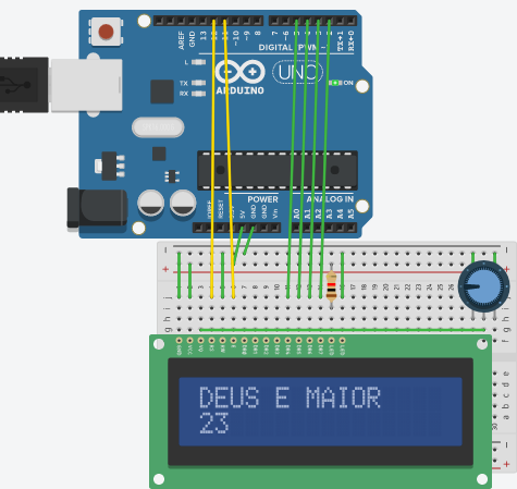
Emulador feito no tinkercad.com


#define pinA 10
#define pinB 9
#define pinC 6
#define pinD 7
#define pinE 8
#define pinF 11
#define pinG 12
#define pinPD 5
#define pinBotao 2

int numero = 10;
boolean botaoAtu = false;
boolean botaoAnt = false;

void setup() {
  // put your setup code here, to run once:
  pinMode(pinBotao, INPUT);

  pinMode(pinA, OUTPUT);
  pinMode(pinB, OUTPUT);
  pinMode(pinC, OUTPUT);
  pinMode(pinD, OUTPUT);
  pinMode(pinE, OUTPUT);
  pinMode(pinF, OUTPUT);
  pinMode(pinG, OUTPUT);
  pinMode(pinPD, OUTPUT);

  randomSeed( analogRead(A0) );
}

void loop() {
  // put your main code here, to run repeatedly:
  botaoAtu = digitalRead(pinBotao);

  if (botaoAtu && !botaoAnt) {
     numero = random(10);
  }
  botaoAnt = botaoAtu;

  switch (numero) {
      case 0:
        digitalWrite(pinA, HIGH);
        digitalWrite(pinB, HIGH);
        digitalWrite(pinC, HIGH);
        digitalWrite(pinD, HIGH);
        digitalWrite(pinE, HIGH);
        digitalWrite(pinF, HIGH);
        digitalWrite(pinG, LOW);
        digitalWrite(pinPD, LOW);
        break;

      case 1:
        digitalWrite(pinA, LOW);
        digitalWrite(pinB, HIGH);
        digitalWrite(pinC, HIGH);
        digitalWrite(pinD, LOW);
        digitalWrite(pinE, LOW);
        digitalWrite(pinF, LOW);
        digitalWrite(pinG, LOW);
        digitalWrite(pinPD, LOW);
        break;

      case 2:
        digitalWrite(pinA, HIGH);
        digitalWrite(pinB, HIGH);
        digitalWrite(pinC, LOW);
        digitalWrite(pinD, HIGH);
        digitalWrite(pinE, HIGH);
        digitalWrite(pinF, LOW);
        digitalWrite(pinG, HIGH);
        digitalWrite(pinPD, LOW);
        break;

      case 3:
        digitalWrite(pinA, HIGH);
        digitalWrite(pinB, HIGH);
        digitalWrite(pinC, HIGH);
        digitalWrite(pinD, HIGH);
        digitalWrite(pinE, LOW);
        digitalWrite(pinF, LOW);
        digitalWrite(pinG, HIGH);
        digitalWrite(pinPD, LOW);
        break;

      case 4:
        digitalWrite(pinA, LOW);
        digitalWrite(pinB, HIGH);
        digitalWrite(pinC, HIGH);
        digitalWrite(pinD, LOW);
        digitalWrite(pinE, LOW);
        digitalWrite(pinF, HIGH);
        digitalWrite(pinG, HIGH);
        digitalWrite(pinPD, LOW);
        break;

      case 5:
        digitalWrite(pinA, HIGH);
        digitalWrite(pinB, LOW);
        digitalWrite(pinC, HIGH);
        digitalWrite(pinD, HIGH);
        digitalWrite(pinE, LOW);
        digitalWrite(pinF, HIGH);
        digitalWrite(pinG, HIGH);
        digitalWrite(pinPD, LOW);
        break;

      case 6:
        digitalWrite(pinA, HIGH);
        digitalWrite(pinB, LOW);
        digitalWrite(pinC, HIGH);
        digitalWrite(pinD, HIGH);
        digitalWrite(pinE, HIGH);
        digitalWrite(pinF, HIGH);
        digitalWrite(pinG, HIGH);
        digitalWrite(pinPD, LOW);
        break;

      case 7:
        digitalWrite(pinA, HIGH);
        digitalWrite(pinB, HIGH);
        digitalWrite(pinC, HIGH);
        digitalWrite(pinD, LOW);
        digitalWrite(pinE, LOW);
        digitalWrite(pinF, LOW);
        digitalWrite(pinG, LOW);
        digitalWrite(pinPD, LOW);
        break;

      case 8:
        digitalWrite(pinA, HIGH);
        digitalWrite(pinB, HIGH);
        digitalWrite(pinC, HIGH);
        digitalWrite(pinD, HIGH);
        digitalWrite(pinE, HIGH);
        digitalWrite(pinF, HIGH);
        digitalWrite(pinG, HIGH);
        digitalWrite(pinPD, LOW);
        break;

      case 9:
        digitalWrite(pinA, HIGH);
        digitalWrite(pinB, HIGH);
        digitalWrite(pinC, HIGH);
        digitalWrite(pinD, HIGH);
        digitalWrite(pinE, LOW);
        digitalWrite(pinF, HIGH);
        digitalWrite(pinG, HIGH);
        digitalWrite(pinPD, LOW);
        break;

      default:
        digitalWrite(pinA, LOW);
        digitalWrite(pinB, LOW);
        digitalWrite(pinC, LOW);
        digitalWrite(pinD, LOW);
        digitalWrite(pinE, LOW);
        digitalWrite(pinF, LOW);
        digitalWrite(pinG, LOW);
        digitalWrite(pinPD, HIGH);
        break;
 
  }

  delay(10);
}

Créditos para:  https://cursodearduino.net/

22/01/2020

Programa 17

Função com Arduíno

#define pinLedVm 2
#define pinLedVd 3
#define pinBotao 4

boolean pisca = false;

boolean leBotao(int porta);
void piscaLED(int porta, int tempo);

void setup() {
  pinMode(pinLedVd, OUTPUT);
  pinMode(pinLedVm, OUTPUT);
  pinMode(pinBotao, INPUT_PULLUP);
}

void loop() {

  if (leBotao(pinBotao)) {
     pisca = !pisca;
  }
 

  if (pisca) {
     piscaLED(pinLedVm, 200);
     piscaLED(pinLedVd, 500);
  }
}


boolean leBotao(int porta) {
  static boolean estadoAnterior[14] = {true,true,true,true,true,true,true,true,true,true,true,true,true,true};
   
  boolean estadoBotao = digitalRead(porta);
  boolean ligado = false;
  if (!estadoBotao && estadoAnterior[porta]) {
     ligado = true;
  }
  estadoAnterior[porta] = estadoBotao;

  return ligado;
}


void piscaLED(int porta, int tempo) {
  static unsigned long delay1[14] = {0,0,0,0,0,0,0,0,0,0,0,0,0,0};

  if ((millis() - delay1[porta]) < tempo) {
     digitalWrite(porta, HIGH);
  } else {
     digitalWrite(porta, LOW);
  }

  if ((millis() - delay1[porta]) >= (tempo * 2) ) {
     delay1[porta] = millis();
  }
}

14/01/2020

Programa 16

Delay e millis no Arduíno


#define pinLedVd 10
#define pinLedVm 8
#define pinBotao 2

boolean estadoBotao = true;
boolean estAntBotao = true;
boolean estadoPisca = false;

unsigned long delay1 = 0;

void setup() {
  pinMode(pinLedVd, OUTPUT);
  pinMode(pinLedVm, OUTPUT);
  pinMode(pinBotao, INPUT_PULLUP);

  digitalWrite( pinLedVd, HIGH);
}

void loop() {

  estadoBotao = digitalRead(pinBotao);
  if (!estadoBotao && estAntBotao) {
     estadoPisca = !estadoPisca;
  }
  estAntBotao = estadoBotao;

  if (estadoPisca) {

    if ((millis() - delay1) >= 500) {
       digitalWrite( pinLedVm, HIGH);
    }

    if ((millis() - delay1) < 500) {
       digitalWrite( pinLedVm, LOW);
    }
   
    if ((millis() - delay1) >= 1000) {
      delay1 = millis();
    }
  } else {
    digitalWrite( pinLedVm, LOW);
  }

  delay(10);
}

Programa 15 -

Impressão e contador no Arduíno usando display LCD

Simulação feita no Tinkercad


#include <LiquidCrystal.h>

// initialize the library with the numbers of the interface pins
LiquidCrystal lcd(12, 11, 5, 4, 3, 2);

void setup() {
     // set up the LCD's number of columns and rows:
     lcd.begin(16, 2);
     // Print a message to the LCD.
     lcd.print("DEUS E MAIOR ");
}

void loop() {
     // set the cursor to column 0, line 1
     // (note: line 1 is the second row, since counting begins with 0):
     lcd.setCursor(0, 1);
     // print the number of seconds since reset:
     lcd.print(millis() / 500);
}


Palavras chave:

Printing and counter in Arduino using LCD display
Impresión y contador en Arduino usando pantalla LCD
Priontáil agus cuntar in Arduino ag baint úsáide as taispeáint LCD
Druk en toonbank in Arduino met LCD-skerm
Drukowanie i liczenie w Arduino za pomocą wyświetlacza LCD
Друк та лічильник в Ардуїно за допомогою РК-дисплея
Skriva ut och räknar i Arduino med LCD-skärm
הדפסה ודלפק בארדואינו באמצעות צג LCD
Nyithak lan kontra ing Arduino nggunakake tampilan LCD
Ispis i šalter u Arduinu pomoću LCD zaslona
Печат и брояч в Arduino с помощта на LCD дисплей

13/01/2020

Programa 14 - Letras na tabela ASC

Imprimir caracteres usando while


#define pinBotao 2

void setup() {
  pinMode(pinBotao, INPUT_PULLUP);//PULLUP = evita a nececidade de 1 resistor
  Serial.begin(9600);//comunicação serial
}

void loop() {
  int n3 = 0;

  //laço de números

  for(int n1 = 0; n1 < 50; n1++){
   Serial.print(char((n1 % 10)+48));
   if(digitalRead(pinBotao) == LOW){//se a leitura for igual a desligado
    delay(400);
    break;
   }
   delay(50);
  }
  Serial.println();//pula uma linha

  //LAÇO DAS LETRAS MAIÚSCULAS
  letrasMaiusculas://endereço
  int n2 = 0;
 
  while (n2 < 50){
    //25 letras maíusculas na tabela ASC
    Serial.print(char((n2 % 25)+ 65));
    n2++;
    if(digitalRead(pinBotao) == LOW){
      delay(400);
      continue;//vai enviar para o while novamente
    }
    delay(50);
  }
  Serial.println();

  //laço das letras minúsculas
  do{
    n3 = random(25);//sorteando numero
    Serial.print(char(n3 + 97));//letra de a - z
    if(digitalRead(pinBotao) == LOW){
      delay(400);
      Serial.println();
      n2 = 0;
      goto letrasMaiusculas;//mudar para um endereço especificado
    }
    delay(50);
  }while (n3 != 16);//enquanto não for a letra q minúscula na tabela ASC

  Serial.println();
}

Saída gerada

12/01/2020

Programa 13 - Binario, hexadecimal e octal

Binario, hexadecimal e octal no Arduino

int valor1, valor2, valor3, valor4;

void setup() {
  valor1 = 25;
  valor2 = 13;

  Serial.begin(9600);

  Serial.print("Valor1: = ");
  Serial.print(valor1);

  Serial.print("\nValor2: = ");
  Serial.print(valor2);

  Serial.print("\n\nValor1 em binário = ");//exibe na tela
  Serial.print(valor1, BIN);// imprime o valor1 em binário

  Serial.print("\nValor2 em decimal: = ");
  Serial.print(valor2, DEC);

  Serial.print("\nValor1 em hexadecimal = ");
  Serial.print(valor1, HEX);

  Serial.print("\nValor2 em octal = ");
  Serial.print(valor2, OCT);
}

void loop() {

}

Saída gerada


10/01/2020

Programa 12 - Soma e subtração no Arduino

Soma e subtração no Arduino

int valor1, valor2;
float soma, sub, divi, mult, resto, resFinal;

void setup() {
  valor1 = 25;
  valor2 = 13;

  soma = valor1 + valor2;
  sub = valor1 - valor2;
  divi = valor1 / valor2;
  mult = valor1 * valor2;
  resto = int (valor1) % int(valor2); // convertendo para inteiro

  resFinal = (soma * sub - divi + mult )/resto;

  Serial.begin(9600);
  Serial.print("Valor1: = ");//exibe na tela
  Serial.print(valor1);// imprime o valor1

  Serial.print("\nValor2: = ");
  Serial.print(valor2);

  Serial.print("\n\nSoma: = ");
  Serial.print(soma);

  Serial.print("\nSubtração: = ");
  Serial.print(sub);

  Serial.print("\nDivisaoão: = ");
  Serial.print(divi);

  Serial.print("\nMultiplicação: = ");
  Serial.print(mult);

  Serial.print("\nResto: = ");
  Serial.print(resto);

  Serial.print("\nResultado final: = ");
  Serial.print(resFinal);
}

void loop() {

}

Saída gerada


09/01/2020

Programa 11

Contador usando Arduíno 


//Portas analógicas
int pinos[9] = {12,11,10,9,8,7,6,5,4};
//int pinLed;

float minimo = 65;
float maximo = 1020;
float valorLDR;//guardar o valor nessa variavel
float luminosidade;

void setup() {
  // iniciando o pinLed
  for(int pinLed = 0; pinLed <= 8; pinLed++){
    pinMode(pinos[pinLed], OUTPUT);//portas digitais de saidas que irao ligar e desligar
  }

  pinMode(A0, INPUT);//porta analogica
}

void loop() {
  //
  valorLDR = analogRead(A0);//ler e guardar o valor nessa variavel
  luminosidade = ((valorLDR - minimo)/(maximo - minimo)) * 10;
  luminosidade = (luminosidade - 10) * -1 ;

  //acender a luminosidade de acordo com a faixa
  for(int pinLed = 0; pinLed <= 8; pinLed++){
    if(pinLed < luminosidade){
      digitalWrite(pinos[pinLed], HIGH);//ligar o led
    }else {
      digitalWrite(pinos[pinLed], LOW);//deligar o led
    }
  }
}

Programa 10

Usando Array no Arduíno com sensor de luz


//Portas analógicas
int pinos[9] = {12,11,10,9,8,7,6,5,4};
//int pinLed;

float minimo = 65;
float maximo = 1020;
float valorLDR;//guardar o valor nessa variavel
float luminosidade;

void setup() {
  // iniciando o pinLed
  for(int pinLed = 0; pinLed <= 8; pinLed++){
    pinMode(pinos[pinLed], OUTPUT);//portas digitais de saidas que irao ligar e desligar
  }

  pinMode(A0, INPUT);//porta analogica
}

void loop() {
  //
  valorLDR = analogRead(A0);//ler e guardar o valor nessa variavel
  luminosidade = ((valorLDR - minimo)/(maximo - minimo)) * 10;
  luminosidade = (luminosidade - 10) * -1 ;

  //acender a luminosidade de acordo com a faixa
  for(int pinLed = 0; pinLed <= 8; pinLed++){
    if(pinLed < luminosidade){
      digitalWrite(pinos[pinLed], HIGH);//ligar o led
    }else {
      digitalWrite(pinos[pinLed], LOW);//deligar o led
    }
  }
}

Programa 9

Ligar leds no Arduíno usando Array


int pinLed[9] = {12,11,10,9,8,7,6,5,4};
int numeroLed;
char digitado;

void setup() {
  int x;

  for(int x = 0; x <= 0; x++){
    pinMode(pinLed[x], OUTPUT);
  }

  Serial.begin(9600);
}

void loop() {
  digitado = ' ';
  numeroLed = 0;
 
  while (digitado != 'P'){//enquanto for menor que 8 acrescenta 1
    digitalWrite(pinLed[numeroLed], LOW);//apagou
   
    numeroLed += 1;
    if(numeroLed > 8){//se for maior
      numeroLed = 0;//reseta
    }
    digitalWrite(pinLed[numeroLed], HIGH);

  //verificar se tem alguma informação na porta serial
  if(Serial.available()){//se existir alguma informação na porta serial, se foi enviado informação para o arduino
    digitado = Serial.read();//lendo informação
    }

    delay(50);
  }

  delay(5000);
 
}


08/01/2020

Programa 8

Ascender leds com Arduino usando Array


int pinLed[9] = {12,11,10,9,8,7,6,5,4};
int numeroLed;

void setup() {
  int x;

  for(int x = 0; x <= 0; x++){
    pinMode(pinLed[x], OUTPUT);
  }

}

void loop() {
  numeroLed = 0;

  while (numeroLed <= 8){
    digitalWrite(pinLed[numeroLed], HIGH);
    delay(50);

    numeroLed += 1;
  }

  numeroLed = 8;
  while(numeroLed >= 0){
    digitalWrite(pinLed[numeroLed], LOW);
    delay(500);

    numeroLed -= 1;
  }
}

Créditos para https://cursodearduino.net/

07/01/2020

Programa 7

Soma no Arduíno

int x, y, z, soma;

void setup() {
  // put your setup code here, to run once:
  //arduino começa a se comunicar com o computador
  Serial.begin(9600);//9600 velocidade

  x = 10;
  y = 20;
  z = 50;
  soma = x + y + z;
  Serial.print("Valor de x = ");
  Serial.print(x);

  Serial.print("\nValor de y = ");
  Serial.print(y);

  Serial.print("\nValor de z = ");
  Serial.print(z);

  Serial.print("\nSoma = ");
  Serial.print(soma);
}

void loop() {
  // put your main code here, to run repeatedly:

}

Créditos para https://cursodearduino.net/

Programa 6

Acender sequencial de Leds em Arduino


int pinLed[9] = {12,11,10,9,8,7,6,5,4};//portas
int numeroLed;

void setup() {
  int i;
  //repetir 0 vezes
  for(i =0; i <= 8; i++){
    pinMode(pinLed[i], OUTPUT);//repete várias vezes
  }
}

void loop() {
  //ligar os leds ascendente
  for(numeroLed = 0; numeroLed <=8; numeroLed++){
    digitalWrite(pinLed[numeroLed], HIGH);
    delay(200);
  }

  //desliga decrescente
  for(numeroLed = 8; numeroLed>= 0; numeroLed--){
    digitalWrite(pinLed[numeroLed], LOW);//desliga
    delay(800);
  }

}

Créditos para https://cursodearduino.net/

Programa 5

Acender Led no Arduino com botão de pressão


int pinVermelho = 10;
int pinAmarelo = 9;
int pinVerde = 8;
int pinBotao = 7;
int pinPedestreVermelho = 3;
int pinPedestreVerde = 2;

int faseSemaforo;

int estadoBotao;
int estadoAnteriorBotao;

int tempoPisca;
int estadoPisca;

void setup() {
  // put your setup code here, to run once:

  pinMode(pinVerde, OUTPUT);
  pinMode(pinAmarelo, OUTPUT);
  pinMode(pinVermelho, OUTPUT);
  pinMode(pinBotao, INPUT);
  pinMode(pinPedestreVerde, OUTPUT);
  pinMode(pinPedestreVermelho, OUTPUT);

  faseSemaforo = 1;

  estadoAnteriorBotao = digitalRead(pinBotao);

  tempoPisca = 0;
  estadoPisca = HIGH;
}

void loop() {
  // put your main code here, to run repeatedly:

  estadoBotao = digitalRead(pinBotao);

  if ((estadoBotao == LOW) && (estadoAnteriorBotao == HIGH)) {
   
     if (faseSemaforo < 4) {
       faseSemaforo = faseSemaforo + 1;
     } else {
       faseSemaforo = 1;
     }
  }

  estadoAnteriorBotao = estadoBotao;

  if (faseSemaforo == 1) {    //SEMAFORO ABERTO (VERDE)
     digitalWrite(pinVerde, HIGH);
     digitalWrite(pinAmarelo, LOW);
     digitalWrite(pinVermelho, LOW);

     digitalWrite(pinPedestreVerde, LOW);
     digitalWrite(pinPedestreVermelho, HIGH);   
  }

  if (faseSemaforo == 2) {   //SEMAFORO AMARELO
     digitalWrite(pinVerde, LOW);
     digitalWrite(pinAmarelo, HIGH);
     digitalWrite(pinVermelho, LOW);

     digitalWrite(pinPedestreVerde, LOW);
     digitalWrite(pinPedestreVermelho, HIGH);     
  }

  if (faseSemaforo == 3) {   //SEMAFORO FECHADO (VERMELHO)
     digitalWrite(pinVerde, LOW);
     digitalWrite(pinAmarelo, LOW);
     digitalWrite(pinVermelho, HIGH);
   
     digitalWrite(pinPedestreVerde, HIGH);
     digitalWrite(pinPedestreVermelho, LOW);     
  }

  if (faseSemaforo == 4) {   //SEMAFORO PEDESTRE PISCANDO
     digitalWrite(pinVerde, LOW);
     digitalWrite(pinAmarelo, LOW);
     digitalWrite(pinVermelho, HIGH);

     tempoPisca = tempoPisca + 1;
     if (tempoPisca == 400) {
        estadoPisca = !estadoPisca;
        tempoPisca = 0;
     }
   
     digitalWrite(pinPedestreVerde, LOW);
     digitalWrite(pinPedestreVermelho, estadoPisca);     
   
  }

  delay(100);
}

Créditos para https://cursodearduino.net/

Programa 4

Ascender Led no Arduino com botão de pressão

void setup() {

  pinMode(10, OUTPUT);
  pinMode(9, OUTPUT);
  pinMode(7, INPUT);

}

void loop() {

  int estadoBotao;
  estadoBotao = digitalRead(7);//ao apertar o botão irá controlar os estados do led

  digitalWrite(10, estadoBotao);
  digitalWrite(9, estadoBotao);
}

Créditos para https://cursodearduino.net/

Programa 3

Acender Led em Arduino com intervalo de tempo

void setup() {

  pinMode(10, OUTPUT);
  pinMode(9, OUTPUT);

}

void loop() {

  int intervaloPisca;
  intervaloPisca = 700;

  digitalWrite(10, HIGH);
  digitalWrite(9, LOW);
  delay(intervaloPisca);//500 milesegundos

  digitalWrite(10, LOW);
  digitalWrite(9, HIGH);
  delay(intervaloPisca);
}

Créditos para https://cursodearduino.net/

Programa 2

Acender Led com intervalo de tempo em Arduino

void setup() {
  // put your setup code here, to run once:
  pinMode(10, OUTPUT);
  pinMode(9, OUTPUT);

}

void loop() {
  // put your main code here, to run repeatedly:
  int intervaloPisca;
  intervaloPisca = 700;

  digitalWrite(10, HIGH);
  digitalWrite(9, LOW);
  delay(intervaloPisca);//500 milesegundos

  digitalWrite(10, LOW);
  digitalWrite(9, HIGH);
  delay(intervaloPisca);
}

Créditos para https://cursodearduino.net/

02/01/2020

Programa 1 - Ligar led

Acender Led no arduino

void setup() {
  // put your setup code here, to run once:
  pinMode(10, OUTPUT);//ligar
}

void loop() {
  // put your main code here, to run repeatedly:
  digitalWrite(10, HIGH);//liga
  delay(1000);//a cada 1 seg
  digitalWrite(10, LOW);//desliga
  delay(1000);
}

Créditos para  https://cursodearduino.net/ 

22/12/2019

SAP_Ev2

Simulação do modelo de um SAP1 no Logisim
Autor: Professor Giuliano - Microprocessadores - IFMT - Engenharia da Computação 2019/2
SAP1


Clique aqui para fazer o download do arquivo feito no Logisim versão 2.7

20/12/2019

HashSet em java

package conceito;
import java.util.HashSet;
import java.util.Set;

public class Main1 {

    public static void main(String[] args) {
        // TODO code application logic here
        Set<String> lista = new HashSet<String>();
        lista.add("a");
        lista.add("a");//só vai adicionar elementos não repetidos
        lista.add("b");
        lista.add("c");
        lista.add("d");
        lista.add("d");só vai adicionar elementos não repetidos
       
        for(String s : lista){
            System.out.println(lista);
        }
    }
   
}
Saída gerada


CPU Simples no Logisim


Clique aqui para fazer o download do arquivo feito no Logisim versão 2.7