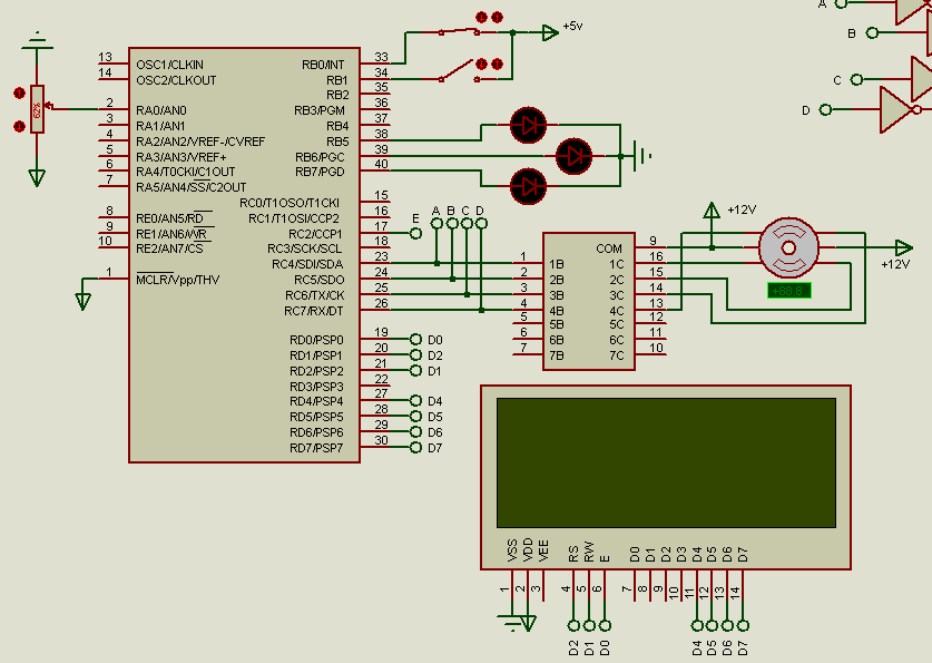
Pesquisar neste blog

Mostrando postagens com marcador Microcontroladores. Mostrar todas as postagens

09/07/2023

LCD CGRAM com método avançado

Objetivo: Fazer uma animação no LCD cgram utilizando matriz para reduzir linhas de código.

LCD cgram com matriz


Código feito em CCS C Compiler

#include <16F877A.h>
#use delay(clock = 20MHz)
#include <lcd.c>
#define LIN 12 // limite que a RAM consegue processar
#define COL 8

int matriz[LIN][COL] = {
{0b00000, 0b00000, 0b00000, 0b00000, 0b00000, 0b00000, 0b00000},
{0b00000, 0b01000, 0b00000, 0b00000, 0b00000, 0b00000, 0b00000},
{0b00000, 0b01110, 0b00000, 0b00000, 0b00000, 0b00000, 0b00000},
{0b00000, 0b01110, 0b00001, 0b00000, 0b00000, 0b00000, 0b00000},
{0b00000, 0b01110, 0b00001, 0b00001, 0b00001, 0b00000, 0b00000},
{0b00000, 0b01110, 0b00001, 0b00001, 0b00001, 0b00001, 0b00000},
{0b00000, 0b01110, 0b00001, 0b00001, 0b00001, 0b00001, 0b00010},
{0b00000, 0b01110, 0b00001, 0b00001, 0b00001, 0b00001, 0b01110},
{0b00000, 0b01110, 0b00001, 0b00001, 0b00001, 0b10001, 0b01110},
{0b00000, 0b01110, 0b00001, 0b00001, 0b10001, 0b10001, 0b01110},
{0b00000, 0b01110, 0b00001, 0b10001, 0b10001, 0b10001, 0b01110},
{0b00000, 0b01110, 0b10001, 0b10001, 0b10001, 0b10001, 0b01110}  
};

void main(){
   lcd_init();
         
   while(TRUE){
   /*
      //matriz[0][i];
      lcd_set_cgram_char(0, matriz[i]);
      printf(lcd_putc, "\f%c \t\ni = %d", 0, i);
      delay_ms(1000);
      
      i++;
      if(i >= LIN){ i = 0;}*/
      for(int i = 0; i < COL; i++){        
         for(int j = 0; j < LIN; j++){
            
            lcd_set_cgram_char(0, matriz[j]);
            lcd_gotoxy(1, 1);
            printf(lcd_putc, "\f%c \t[%d][%d]", 0, i, j);
            
            delay_ms(500);
            
         }
      }
   }
}

18/06/2023

Frequência em motor de passo com PIC 16F877A

Objetivo: Fazer um motor de passo com os seguintes requisitos :
1. O motor de passo deve girar no sentido horário ou anti-horário
2. Sua velocidade de rotação deve ser controlada por um potenciômetro
3. Deve ser acionada por 2 botões
4. Deve ser informada os dados no display LCD:
  • Posição do ângulo
  • Dados da frequência angular em que está girando
  • Dados da frequência em Hz em que está girando
5. Se o motor estiver off, deverá ser acionado 1 Led e desligar os demais
6. Se o motor estiver ON no sentido horário deverá ser acionado o Led 2 e desligar os demais
7, Se o motor estiver ON no sentido anti-horário, deverá ser acionado o Led 3 e desligar os demais
8. Se o motor estiver off, deverá informar no Display LCD a quantidade de tempo e dias parado.

Resolução feita em CCS C Compiler e software Protheus
Circuito para identificar 1 ciclo de trabalho


Circuito


Simulação feita no Protheus 7.9


CÓDIGO FEITO EM CCS C Compiler

#include <16F877A.h>
#device adc = 8
#use delay(clock = 20MHz)
#FUSES NOWDT, HS, NOPUT, NOPROTECT, NODEBUG, BROWNOUT, NOLVP, NOCPD, NOWRT, NOWRT
#include <lcd.c>
#define size 8

#define PIN_1 PIN_C4
#define PIN_2 PIN_C5
#define PIN_3 PIN_C6
#define PIN_4 PIN_C7

unsigned int A, B, i = 0, POSITION;
unsigned int16 VALUE;
unsigned int8 MOTOR[size] = {64, 96, 32, 48, 16, -112, -128, -64};
unsigned int16 posicao1[size] = {45, 90, 135, 180, 225, 270, 315, 360};
unsigned int16 posicao2[size] = {360, 315, 270, 225, 180, 135, 90, 45};
unsigned int DIAS, HORAS, MINUTOS, SEGUNDOS = 0;

char setaH[size] = {
    0b00000,
    0b00100,
    0b00110,
    0b11111,
    0b00110,
    0b00100,
    0b00000,
    0b00000
};

char setaA[size] = {
    0b00000,
    0b00100,
    0b01100,
    0b11111,
    0b01100,
    0b00100,
    0b00000,
    0b00000
};

char graus[size] = {
   0b00110,
   0b01001,
   0b00110,
   0b00000,
   0b00000,
   0b00000,
   0b00000,
   0b00000
};

int1 nuevopulso = 0, cambio = 0;
int16 TFB = 0, TFS = 0, TF = 0;
float TEMPO = 0.0, frequencia;

#int_ccp1
void ccp1_int(){
   if(cambio == 0){
      TFS = CCP_1;
      setup_ccp1(CCP_CAPTURE_RE);
      cambio = 1;
   }else{
      TFB = CCP_1;
      setup_ccp1(CCP_CAPTURE_RE);
      cambio = 0;
      
      if(nuevopulso == 0){
         nuevopulso = 1;
      }
   }
}

#INT_TIMER0
void  TIMER0_isr(void) {
   
   if (nuevopulso >= 1){
      TF = (TFB - TFS);
      TEMPO = TF * 1.0 / 1000.0;
      frequencia = 1.0 / (TEMPO / 1000.0);
      nuevopulso = 0;
   }
   
}

#INT_TIMER1
void  TIMER1_isr(void) {
   A = input(PIN_B0);
   B = input(PIN_B1);
   
}

void main(){
   
   setup_adc_ports(AN0);
   setup_adc(ADC_CLOCK_DIV_2);
   setup_timer_0(T1_DIV_BY_1); 
   setup_timer_1(T1_INTERNAL|T1_DIV_BY_1);      //13,1 ms overflow
   
   setup_ccp1(CCP_CAPTURE_RE);
   enable_interrupts(int_ccp1);
   
   enable_interrupts(INT_TIMER1);
   enable_interrupts(INT_TIMER0);
   enable_interrupts(GLOBAL);
      
   lcd_init();
   lcd_set_cgram_char(4, graus);
   
   while(TRUE) {
      output_high(PIN_B5);
      output_low(PIN_B6);
      output_low(PIN_B7);
      
      SEGUNDOS++;
      if ( SEGUNDOS > 59 ){SEGUNDOS = 0 ; MINUTOS++ ;}
      if ( MINUTOS > 59 ){MINUTOS = 0 ; HORAS++ ; }
      if ( HORAS > 23 ) {HORAS = 0 ; DIAS++ ; }
           
      lcd_gotoxy(1, 1);
      printf(lcd_putc,"\f\t\t\tMOTOR OFF !");
      
      lcd_gotoxy(1, 2);
      printf(lcd_putc, "%02u:%02u:%02u",HORAS, MINUTOS, SEGUNDOS);
      
      lcd_gotoxy(21, 1);
      printf(lcd_putc, "DIAS PARADO: %u",DIAS);
      
      delay_ms(1000);
      
      while(A == 1 && B == 0){
         output_high(PIN_B6);
         output_low(PIN_B7);
         output_low(PIN_B5);
         
         VALUE = read_adc();
         
         lcd_set_cgram_char(2, setaH);
         lcd_gotoxy(1, 1);
         printf(lcd_putc, "\f\t\tMOTOR ON ! \t%c", 2);
         
         lcd_gotoxy(1, 2);
         printf(lcd_putc,"ANGULO = [%lu%c]" posicao1[i], 4);
         
         lcd_gotoxy(21, 1);
         printf(lcd_putc,"W = %.2f rad/s", frequencia * 2 * 3.1415);
         
         lcd_gotoxy(21, 2);
         printf(lcd_putc, "F = %.2f Hz", frequencia);
         
         POSITION = MOTOR[i];
         output_bit(PIN_1, POSITION & 16);
         output_bit(PIN_2, POSITION & 32);
         output_bit(PIN_3, POSITION & 64);
         output_bit(PIN_4, POSITION & 128);
         i = (i + 1) % (sizeof(MOTOR) / sizeof(int));
         
         delay_ms(VALUE);
      }
      
      while(A == 0 && B == 1){
         output_high(PIN_B7);
         output_low(PIN_B6);
         output_low(PIN_B5);
         
         VALUE = read_adc();
         
         lcd_set_cgram_char(3, setaA);
         lcd_gotoxy(1, 1);
         printf(lcd_putc, "\f%c\tMOTOR ON !", 3);
         
         lcd_gotoxy(1, 2);
         printf(lcd_putc,"ANGULO = [-%lu%c]" posicao2[i], 4);
         
         lcd_gotoxy(21, 1);
         printf(lcd_putc,"W = %.2f rad/s", frequencia * 2 * 3.1415);
         
         lcd_gotoxy(21, 2);
         printf(lcd_putc, "F = %.2f Hz", frequencia);
         
         POSITION = MOTOR[i];
         output_bit(PIN_4, POSITION & 128);
         output_bit(PIN_3, POSITION & 64);
         output_bit(PIN_2, POSITION & 32);
         output_bit(PIN_1, POSITION & 16);
         i = (i - 1) % (sizeof(MOTOR) / sizeof(int));
         
         delay_ms(VALUE);
      }
      
   }
}

09/06/2023

Mini teste 1 2022/2

1. Projete o circuito e o programa (compilador CCS) de um sistema baseado no microcontrolador PIC16F877A que faça a leitura da entrada analógica PIN_A0, via conversor AD configurado em 8 bits. O  sistema deve apresentar 7 níveis de alerta através de um dispositivo de 3 segmentos (figura 1).


RESOLUÇÃO FEITA EM CCS C Compiler:


#include <16F877A.h>
#device adc = 8
#use delay(clock = 20M)
#fuses XT, NOWDT, NOPROTECT, NOBROWNOUT, NOLVP, NOCPD, NOWRT, NODEBUG
#include <lcd.c>
unsigned int8 analog ;

#INT_TIMER0
void TIMER0_isr(void){
   if (analog >= 127 && analog < 142){ // N1
      output_low(PIN_B5);
      output_low(PIN_B6);
      output_toggle(PIN_B7);
   }
   if (analog >= 175 && analog < 191) { // N4
      output_toggle(PIN_B5);
      output_low(PIN_B6);
      output_low(PIN_B7);
   }
   if (analog >= 159 && analog < 175) { // N3
      output_low(PIN_B5);
      output_toggle(PIN_B6);
      output_toggle(PIN_B7);
   }
   if (analog >= 191 && analog < 207) { // N5
      output_toggle(PIN_B5);
      output_low(PIN_B6);
      output_toggle(PIN_B7);
   }
   if (analog >= 143 && analog < 159) { // N2
      output_low(PIN_B5);
      output_toggle(PIN_B6);
      output_low(PIN_B7);
   }
   if (analog >= 207 && analog < 223) { // N6
      output_toggle(PIN_B5);
      output_toggle(PIN_B6);
      output_low(PIN_B7);
   }
   if (analog >= 223 && analog < 239) { // N7
      output_toggle(PIN_B5);
      output_toggle(PIN_B6);
      output_toggle(PIN_B7);
   }
   
}

void main(){
   // Configuração do LCD
   lcd_init();

   // Configuração do ADC
   setup_adc_ports(AN0);
   setup_adc(ADC_CLOCK_DIV_8);
   set_adc_channel(0);
   
   setup_psp(PSP_DISABLED);
   setup_spi(SPI_SS_DISABLED);
   setup_timer_0(RTCC_INTERNAL | RTCC_DIV_2); // overflow 51,2 u
   setup_comparator(NC_NC_NC_NC);
   setup_vref(FALSE);
   enable_interrupts(INT_TIMER0);
   enable_interrupts(GLOBAL);
   
   while (1){
      analog = read_adc();
      printf(lcd_putc, "\fLeitura: %u", analog);
      delay_ms(1000); 
   }
}

Saída gerada


2. Faça o circuito e o programa (compilador CCS) que liga um LED 1 e desliga o LED 2 quando um botão (Bot1) estiver apertado e desligar LED1 e liga o LED 2 se o botão (Bot1) estiver solvo. Os LED 3, 4 e 5 devem ficar piscando com frequências de 1.3, 2 e 3.5 vezes n Hz. Onde n é igual a soma do último e penúltimo número da sua matrícula.


RESOLUÇÃO FEITA EM CCS C Compiler :

#include <16F877A.h>
#use delay(clock = 20MHz)

// Configuração do microcontrolador
#fuses XT, NOWDT, NOPROTECT, NOBROWNOUT, NOLVP, NOCPD, NOWRT, NODEBUG
#include <lcd.c>
// Variáveis globais
int flag1 = 0, flag2 = 0;
unsigned int16 cont1 = 0, cont2 = 0, cont3 = 0;

#int_TIMER0
void TIMER0_isr(){
   if(flag1 == 0 && flag2 == 1 && ++cont1 >= 85){
      cont1 = 0; output_toggle(PIN_B5); // 114 Hz
   }
   if(flag1 == 0 && flag2 == 1 && ++cont2 >= 55){
      cont2 = 0; output_toggle(PIN_B6); // 176 HZ
   }
   if(flag1 == 0 && flag2 == 1 && ++cont3 >= 32){
      cont3 = 0; output_toggle(PIN_B7); // 308 Hz
   }
   
}
// Função de tratamento da interrupção do TIMER1
#int_timer1
void timer1InterruptHandler(){
   if (input(PIN_B0) == 1){
      flag1 = 1;
      flag2 = 0;
      output_high(PIN_B3);
      output_low(PIN_B4);
      
   }
   if(input(PIN_B1) == 1){
      flag1 = 0;
      flag2 = 1;
      output_low(PIN_B3);
      output_high(PIN_B4);
   }
   
   // Limpa a flag de interrupção do TIMER1
   clear_interrupt(INT_TIMER1);
}

void main(){
   // Configuração do TIMER1
   setup_timer_1(T1_INTERNAL | T1_DIV_BY_1);
   
   // Configuração das interrupções
   enable_interrupts(INT_TIMER1); // Habilita a interrupção do TIMER1
   enable_interrupts(GLOBAL);    // Habilita todas as interrupções globais
   
   setup_timer_0(RTCC_INTERNAL | RTCC_DIV_1); // overflow 51,2 us
   setup_comparator(NC_NC_NC_NC);
   setup_vref(FALSE);
   enable_interrupts(INT_TIMER0);
   
   lcd_init();
   
   while (1){
      printf(lcd_putc,"\f%d : %d",flag1, flag2);
      delay_ms(50);
      
   }
}

Saída gerada


16/05/2023

Sequência de outputs com PIC 16F877A

Objetivo: Dar outputs com apenas 4 pinos do PIC sem comprometer os demais pinos e sem utilizar vários high e low.

CÓDIGO FEITO EM CCS C COMPILER

#include <16F877A.h>
#use delay(clock = 20MHz)

#define size 8

int sequences[][2] = {
  {PIN_B4, 1}, {PIN_B5, 0}, {PIN_B6, 0}, {PIN_B7, 1},
  {PIN_B4, 0}, {PIN_B5, 1}, {PIN_B6, 1}, {PIN_B7, 1},
  {PIN_B4, 0}, {PIN_B5, 0}, {PIN_B6, 0}, {PIN_B7, 0},
  {PIN_B4, 1}, {PIN_B5, 0}, {PIN_B6, 1}, {PIN_B7, 1}, 
  {PIN_B4, 0}, {PIN_B5, 0}, {PIN_B6, 0}, {PIN_B7, 0}, 
  {PIN_B4, 0}, {PIN_B5, 0}, {PIN_B6, 0}, {PIN_B7, 1},
  {PIN_B4, 1}, {PIN_B5, 1}, {PIN_B6, 0}, {PIN_B7, 1},
  {PIN_B4, 0}, {PIN_B5, 0}, {PIN_B6, 1}, {PIN_B7, 0}, 
  {PIN_B4, 0}, {PIN_B5, 0}, {PIN_B6, 0}, {PIN_B7, 1},
  {PIN_B4, 1}, {PIN_B5, 0}, {PIN_B6, 1}, {PIN_B7, 1}};

void set_outputs(int outputs[][2], int num_outputs) {
   
    for (int i = 0; i < num_outputs; i++) {
        output_low(outputs[i][0]);
        output_high(outputs[i][1]);
        delay_ms(500);
    }
}

int main() {
      
   for (int i = 0; i < size; i++) {
       set_outputs(sequences[i], 4);
   } 
   
}

Saída gerada

13/05/2023

Motor de passo com frequência - PIC 16F877A

Objetivo: Fazer um programa que rede no PIC 16F877A para girar com determinada velocidade o motor no sentido horário ao pressionar o botão e ao pressionar novamente o botão ele gire no sentido anti - horário. Deverá ser mostrado a frequência em que o motor está girando.

Saída gerada no softwae Proteus


#include <16F877A.h>
#device adc = 10
#fuses HS, NOWDT, NOPROTECT, NOBROWNOUT, NOLVP, NOCPD, NOWRT
#use delay(clock = 20MHz)
#define size 8
#define T1 300
#define T2 200

#define LCD_DB4   PIN_D4
#define LCD_DB5   PIN_D5
#define LCD_DB6   PIN_D6
#define LCD_DB7   PIN_D7
#define LCD_E     PIN_D0
#define LCD_RS    PIN_D1

#include <lcd.c>
#byte PIR1 = 0x0C

unsigned int cont = 0, speed;
int1 nuevopulso = 0, cambio;
int16 TFB = 0, TFS, TF = 0;
float AP = 0.0, frequencia;

#INT_EXT
void EXT_isr(void) {
   cont++;
   if(cont >= 4){
      cont = 0;
   }
}

#int_ccp1
void ccp1_int(){
   if (cambio == 0 ){
      TFS = CCP_1;
      setup_ccp1(CCP_CAPTURE_RE);
      cambio = 1;
   }else{
      TFB = CCP_1;
      setup_ccp1(CCP_CAPTURE_RE);
      cambio = 0;
      
      if (nuevopulso == 0){
         nuevopulso = 1;
      }
   }
}


void main(){
   setup_timer_1(T1_INTERNAL);
   setup_ccp1(CCP_CAPTURE_RE);
   cambio = 0;
   enable_interrupts(int_ccp1);
   
   enable_interrupts(GLOBAL);
   enable_interrupts(INT_EXT);
   
   setup_adc(ADC_CLOCK_DIV_32);  // Set ASC conversion time to 32 Tosc
   setup_adc_ports(AN0);         // Configure AN0 as analog
   set_adc_channel(0);
   delay_ms(100);
   
   lcd_init();
   
   while(true){
       printf(lcd_putc,"\f\t\tMOTOR OFF !");
       delay_ms(15);
       
       while(cont == 1){
         speed = read_adc();
         if (speed < 2){
            speed = 2;
         }
         
         output_low(PIN_B7);
         output_low(PIN_B5);
         output_low(PIN_B4);
         output_high(PIN_B6);
         if (nuevoPulso >= 1){
            TF = TFB - TFS ;
            AP = TF * 1.0 / 1000.0;
            frequencia = 1.0 / (AP / 1000.0);
            nuevopulso = 0;
         }
         /*lcd_gotoxy(1, 1);
         printf(lcd_putc, "\t\tSENTIDO HORARIO");
         lcd_gotoxy(1, 2);
         printf(lcd_putc, "Pulso = %f ms", AP);
         lcd_gotoxy(21, 1);
         printf(lcd_putc, "Freq = %0.2f Hz", frequencia); */
         delay_ms(speed);
         
         
         output_low(PIN_B7);
         output_low(PIN_B5);
         output_low(PIN_B4);
         output_high(PIN_B6);
         output_high(PIN_B5);
         if (nuevoPulso >= 1){
            TF = TFB - TFS ;
            AP = TF * 1.0 / 1000.0;
            frequencia = 1.0 / (AP / 1000.0);
            nuevopulso = 0;
         }        
         /*lcd_gotoxy(1, 1);
         printf(lcd_putc, "\t\tSENTIDO HORARIO");
         lcd_gotoxy(1, 2);
         printf(lcd_putc, "Pulso = %f ms", AP);
         lcd_gotoxy(21, 1);
         printf(lcd_putc, "Freq = %0.2f Hz", frequencia); */   
         delay_ms(speed);
         
         
         output_low(PIN_B7);
         output_low(PIN_B6);
         output_low(PIN_B4);
         output_high(PIN_B5);
         if (nuevoPulso >= 1){
            TF = TFB - TFS ;
            AP = TF * 1.0 / 1000.0;
            frequencia = 1.0 / (AP / 1000.0);
            nuevopulso = 0;
         }
         /*lcd_gotoxy(1, 1);
         printf(lcd_putc, "\t\tSENTIDO HORARIO");
         lcd_gotoxy(1, 2);
         printf(lcd_putc, "Pulso = %f ms", AP);
         lcd_gotoxy(21, 1);
         printf(lcd_putc, "Freq = %0.2f Hz", frequencia); */
         delay_ms(speed);
         
         
         output_low(PIN_B7);
         output_low(PIN_B6);
         output_high(PIN_B5);
         output_high(PIN_B4);
         if (nuevoPulso >= 1){
            TF = TFB - TFS ;
            AP = TF * 1.0 / 1000.0;
            frequencia = 1.0 / (AP / 1000.0);
            nuevopulso = 0;
         }
         /*lcd_gotoxy(1, 1);
         printf(lcd_putc, "\t\tSENTIDO HORARIO");
         lcd_gotoxy(1, 2);
         printf(lcd_putc, "Pulso = %f ms", AP);
         lcd_gotoxy(21, 1);
         printf(lcd_putc, "Freq = %0.2f Hz", frequencia); */
         delay_ms(speed);
         
         
         output_low(PIN_B7);
         output_low(PIN_B6);
         output_low(PIN_B5);
         output_high(PIN_B4);
         if (nuevoPulso >= 1){
            TF = TFB - TFS ;
            AP = TF * 1.0 / 1000.0;
            frequencia = 1.0 / (AP / 1000.0);
            nuevopulso = 0;
         }        
         /*lcd_gotoxy(1, 1);
         printf(lcd_putc, "\t\tSENTIDO HORARIO");
         lcd_gotoxy(1, 2);
         printf(lcd_putc, "Pulso = %f ms", AP);
         lcd_gotoxy(21, 1);
         printf(lcd_putc, "Freq = %0.2f Hz", frequencia); */
         delay_ms(speed);
         
         
         output_low(PIN_B6);
         output_low(PIN_B5);
         output_high(PIN_B4);
         output_high(PIN_B7);
         if (nuevoPulso >= 1){
            TF = TFB - TFS ;
            AP = TF * 1.0 / 1000.0;
            frequencia = 1.0 / (AP / 1000.0);
            nuevopulso = 0;
         }
         /*lcd_gotoxy(1, 1);
         printf(lcd_putc, "\t\tSENTIDO HORARIO");
         lcd_gotoxy(1, 2);
         printf(lcd_putc, "Pulso = %f ms", AP);
         lcd_gotoxy(21, 1);
         printf(lcd_putc, "Freq = %0.2f Hz", frequencia); */
         delay_ms(speed);
         
         
         output_low(PIN_B6);
         output_low(PIN_B5);
         output_low(PIN_B4);
         output_high(PIN_B7);
         if (nuevoPulso >= 1){
            TF = TFB - TFS ;
            AP = TF * 1.0 / 1000.0;
            frequencia = 1.0 / (AP / 1000.0);
            nuevopulso = 0;
         }
         delay_ms(speed);
         
         output_low(PIN_B4);
         output_low(PIN_B5);
         output_high(PIN_B6);
         output_high(PIN_B7);
         if (nuevoPulso >= 1){
            TF = TFB - TFS ;
            AP = TF * 1.0 / 1000.0;
            frequencia = 1.0 / (AP / 1000.0);
            nuevopulso = 0;
         }
         lcd_gotoxy(1, 1);
         printf(lcd_putc, "\t\tSENTIDO HORARIO");
         lcd_gotoxy(1, 2);
         printf(lcd_putc, "Pulso = %f ms", AP);
         lcd_gotoxy(21, 1);
         printf(lcd_putc, "Freq = %0.2f Hz", frequencia);
         lcd_gotoxy(21, 2);
         printf(lcd_putc, "W = %0.2f rad/s", frequencia * 2 * 3.15);
         delay_ms(speed);
         
       }
       
       while( cont == 3 ){
         speed = read_adc();
         if (speed < 2){
            speed = 2;
         }
                  
         output_low(PIN_B4);
         output_low(PIN_B5);
         output_high(PIN_B6);
         output_high(PIN_B7);
         
         delay_ms(speed);
                     
                         
         output_low(PIN_B4);
         output_low(PIN_B5);
         output_low(PIN_B6);
         output_high(PIN_B7);
         delay_ms(speed);
         
         
         output_low(PIN_B5);
         output_low(PIN_B6);
         output_high(PIN_B4);
         output_high(PIN_B7);
         delay_ms(speed);
         
         
         output_low(PIN_B5);
         output_low(PIN_B6);
         output_low(PIN_B7);
         output_high(PIN_B4);
         delay_ms(speed);
         
         
         output_low(PIN_B6);
         output_low(PIN_B7);
         output_high(PIN_B4);
         output_high(PIN_B5);
         delay_ms(speed);
         
         
         output_low(PIN_B4);
         output_low(PIN_B6);
         output_low(PIN_B7);
         output_high(PIN_B5);
         delay_ms(speed);
         
         
         output_low(PIN_B4);
         output_low(PIN_B7);
         output_high(PIN_B5);
         output_high(PIN_B6);
         delay_ms(speed);
         
         
         output_low(PIN_B4);
         output_low(PIN_B6);
         output_low(PIN_B7);
         output_high(PIN_B6);
         if (nuevoPulso >= 1){
            TF = TFB - TFS ;
            AP = TF * 1.0 / 1000.0;
            frequencia = 1.0 / (AP / 1000.0);
            nuevopulso = 0;
         }
         lcd_gotoxy(1, 1);
         printf(lcd_putc, "SENTIDO ANTI-HORARIO");
         lcd_gotoxy(1, 2);
         printf(lcd_putc, "Pulso = %f ms", AP);
         lcd_gotoxy(21, 1);
         printf(lcd_putc, "Freq = %0.2f Hz", frequencia);
         lcd_gotoxy(21, 2);
         printf(lcd_putc, "W = %0.2f rad/s", frequencia * 2 * 3.15);
         delay_ms(speed);
         
       }
   }
}

07/05/2023

Pulso e Frequência com PIC 16F877A

CÓDIGO FEITO EM CCS C Compiler

#include <16F877A.h>
#fuses XT, NOWDT
#use delay(clock = 4MHz)
#include <lcd.c>

int1 nuevoPulso = 0;
int16 inicioPulso = 0, fimPulso = 0, duracaoPulso = 0;
float periodo = 0.0, frequencia = 0.0;

#int_ccp1
void ccp1_int(){
   if (!nuevoPulso){
      inicioPulso = CCP_1;
      nuevoPulso = 1;
   }
   else{
      fimPulso = CCP_1;
      nuevoPulso = 0;
      
      duracaoPulso = fimPulso - inicioPulso;
   }
}

void calcularPeriodoFrequencia(){
   periodo = duracaoPulso * 1.0 / 1000.0;
   frequencia = 1.0 / (periodo / 1000.0);
}

void main(){
   lcd_init();
   setup_timer_1(T1_INTERNAL);
   setup_ccp1(CCP_CAPTURE_RE);
   enable_interrupts(int_ccp1);
   enable_interrupts(global);
   
   while (TRUE){
      if (nuevoPulso){
         calcularPeriodoFrequencia();
         printf(lcd_putc, "\fPulso = %.2f ms\nFreq= %.2f Hz", periodo, frequencia);
         delay_ms(50);
         nuevoPulso = 0;
      }
   }
}

Saída gerada

12/03/2023

Prova 1 #2022/1

1.1. Crie um programa e faça as ligações necessárias para que os LED liguem e desliguem com frequências iguais as indicadas a seguir:

LED1 = 5Hz         Vi >= 0 e Vi  < 0,8v
LED2 = 10Hz         Vi >= 0,8 e Vi < 1,6v
LED3 = 20Hz         Vi >= 1,6 e Vi < 2,4v
LED4 = 50Hz         Vi >= 2,4 e Vi < 3,2v
LED5 = 100Hz Vi >= 3,2 e Vi < 4v
LED6 =                    Liga quando Vi >= 4v


Resolução feita no CCS C Compiler

#include <16F877A.h>
#device adc = 8
#FUSES NOWDT, HS, NOPUT, NOPROTECT, NODEBUG, BROWNOUT, NOLVP, NOCPD, NOWRT, NOWRT
#use delay(clock = 20MHz)
#include <lcd.c>
#use standard_io (b)
/*Crie um programa e faça as ligações para que os LED liguem e desliguem com 
frequências iguais as indicadas a seguir:
LED1 = 5HZz Vi >= 0V e Vi < 0,8V
LED2 = 10Hz Vi >= 0,8V e Vi < 1,6V
LED3 = 20HZ Vi >= 1,6 e Vi < 2,4V
LED4 = 50HZ Vi >= 2,4 e Vi < 3,2V
LED5 = 100HZ Vi >= 3,2 e Vi < 4V
LED6 = Liga quando Vi >= 4V
*/
unsigned int8 analog, frequencia, tempo;
float tensao;
unsigned int16 cont0 = 0, cont1 = 0, cont2 = 0, cont3 = 0, cont4 = 0, cont5 = 0;

#int_TIMER0
void TIMER0_isr(float tensao){
         
   if(tensao >= 0.01 && tensao < 0.8){
      printf(lcd_putc,"\fTENSAO = %1.2f V\nFREQ= 5 Hz", tensao);      
      if(++cont1 >= 1970) {cont1 = 0; output_toggle(PIN_B0);}   // 5HZ   ok
      
   }else if(tensao >= 0.80 && tensao < 1.60){
      printf(lcd_putc,"\fTENSAO = %1.2f V\nFREQ= 10 Hz", tensao); 
      if(++cont2 >= 750) {cont2 = 0; output_toggle(pin_B1);}   //10 HZ  ok
      
   }else if(tensao >= 1.60 && tensao < 2.40){
      printf(lcd_putc,"\fTENSAO = %1.2f V\nFREQ= 20 Hz", tensao); 
      if(++cont3 >= 240) {cont3 = 0; output_toggle(pin_B2);}   // 20 Hz  
      
   }else if(tensao >= 2.40 && tensao < 3.20){
      printf(lcd_putc,"\fTENSAO = %1.2f V\nFREQ= 50 Hz", tensao); 
      if(++cont4 >= 98) {cont4 = 0; output_toggle(pin_B3);}   // 50 Hz
      
   }else if(tensao >= 3.20 && tensao < 4.0){
      printf(lcd_putc,"\fTENSAO = %1.2f V\nFREQ= 100 Hz", tensao); 
      if(++cont5 >= 39) {cont5 = 0; output_toggle(pin_B4);}    // 100 Hz
   }else if(tensao >= 4.0){
      output_high(PIN_B5);
   }
   
}

void main(){
   setup_adc_ports(NO_ANALOGS);
   setup_adc(ADC_OFF);
   setup_psp(PSP_DISABLED);
   setup_spi(SPI_SS_DISABLED);   
   setup_timer_0(RTCC_INTERNAL|RTCC_DIV_1);
   setup_timer_1(T1_DISABLED);
   setup_timer_2(T2_DISABLED, 0, 1);
   setup_comparator(NC_NC_NC_NC);
   setup_vref(FALSE);
   setup_adc(ADC_CLOCK_DIV_32);           // Set ADC conversion time to 32Tosc
   setup_adc_ports(AN0);          // Configure AN0,AN1 and AN3 as analog   
   set_adc_channel(0);                    // Select channel AN1     
   enable_interrupts(INT_TIMER0);
   enable_interrupts(GLOBAL);
   lcd_init();
   
   while(true) {
      analog = read_adc();
      tensao = (5.0 / 255.0) * analog;
      printf(lcd_putc,"\fTENSAO = %1.2f V\nT= %ums \tFREQ= %uHz",tensao, tempo, frequencia);
            
      TIMER0_isr(tensao);
            
   }
}


2. 2. Crie um programa e faça as ligações (cristal, resistor, alimentação, ...) necessárias para que os displays apresentem uma luz circulante no sentido horário (a, b, c, d, d', e', f', a', a, b,...). Onde d', e', f' e a', são segmento do display  catodo comum. A velocidade dependerá da posição do potenciômetro.


Resolução em código feito no CCS C Compiler

#include <16F877A.h>
#device adc = 8
#use delay(clock = 20MHz)
#FUSES HS,NOWDT,NOPROTECT,NOLVP

unsigned int8 vet1[] = {0b00001000, 0b00010000, 0b00100000, 0b00000001};
unsigned int8 vet2[] = {0b11111110, 0b11111101, 0b11111011, 0b11110111};

int size = sizeof(vet1)/sizeof(int); // tamanho do vetor vet1
unsigned int16 leia;

void main(void){
  setup_adc(ADC_CLOCK_DIV_32);           // Set ADC conversion time to 32Tosc
  setup_adc_ports(AN0_AN1_AN3);          // Configure AN0,AN1 and AN3 as analog
  setup_ccp2(CCP_PWM);                   // Configure CCP2 as a PWM
  setup_timer_2(T2_DIV_BY_16, 255, 1);   // Set PWM frequency to 488Hz
  set_adc_channel(0);                    // Select channel AN1
  
  while(true){
                        
      leia = read_adc();                 // Read from AN1 and store in j
      
      for(int i = 0; i < size; i++){
         output_d(vet1[i]);
         delay_ms(leia);
      }      
      
      for(int j = 0; j < size; j++){
         output_d(vet2[j]);
         delay_ms(leia);
      }
   }
}


3. Desenvolva um programa para acionar o motor de passo a seguir. Para girar no sentido 1 (b1, b2, b3, b4, b1, b2,...) e no sentido contrário devem ser acionadas as bobinas (b4, b3, b2, b1, b4, b3,...) Utilize um botão para inverter o sentido. O motor deve girar com velocidade de 100 rpm (rpm = rotações por minuto) no sentido horário e 75 rpm no sentido anti-horário.


Resolução feita no CCS C Compiler

#include <16F877A.h>
#fuses XT, HS,NOWDT,NOPROTECT,NOLVP
#use delay(clock = 20MHz)
#include <lcd.c>

#define t1 150
#define t2 200

#use fast_io(B)

unsigned int horario[9] = {0b00010000, 0b00110000, 0b01110000, 0b01100000, 0b11100000, 0b11000000, 0b10000000, 0b10010000};
unsigned int antiHorario[9] = {0b10000000, 0b11000000, 0b01000000, 0b01100000, 0b00100000, 0b00110000, 0b00010000, 0b10010000};
int i = 0, cont = 0;

#INT_EXT
ext_isr(){
   cont++;
   if(cont >= 4) {cont = 0;}
}

void main(){
   set_tris_b(0x01);
   output_low(PIN_B7);
   port_b_pullups(TRUE);
   enable_interrupts(int_ext);
   ext_int_edge(L_TO_H);
   enable_interrupts(GLOBAL);
   
   lcd_init();
   
   while(true){
      printf(lcd_putc, "\fMOTOR OFF !");
      delay_ms(500);
   
      while(cont == 1){
         output_b(horario[i]);
         lcd_gotoxy(1, 1);
         delay_ms(t1);
         i++;
         if(++i >= 8) {i = 0;}
         
         lcd_gotoxy(1, 1);
         printf(lcd_putc, "\fMOTOR ON");
         lcd_gotoxy(1,2);
         printf(lcd_putc, "SENTIDO HORARIO");
         lcd_gotoxy(21,1);
         printf(lcd_putc, "Freq = 100 RPM");
         lcd_gotoxy(21,2);
         printf(lcd_putc, "Freq = 10.47 rad/s");
      }
   
      while(cont == 3){
         output_b(antiHorario[i]);
         delay_ms(t2);
         i++;
         if(++i >= 8) {i = 0;}
         
         lcd_gotoxy(1, 1);
         printf(lcd_putc, "\fMOTOR ON");
         lcd_gotoxy(1,2);
         printf(lcd_putc, "SENTIDO ANTI-HORARIO");
         lcd_gotoxy(21,1);
         printf(lcd_putc, "Freq = 75 RPM");
         lcd_gotoxy(21,2);
         printf(lcd_putc, "Freq = 7.85 rad/s");
      }
   }
}

Software Proteus versão 7.9


10/03/2023

Comunicação serial com PIC 16F628A e 18F4550

Código feito em CCS C Compiler

Arquivo: 16F628A.c

#include <16F628A.h>
#fuses INTRC, NOWDT, NOMCLR
#use delay(clock = 4MHz)

#use rs232(baud= 9600, xmit= PIN_B2, rcv= PIN_B1)

void main(){
   
   int1 btn1, btn2, btn3;
   
   while(true){
      btn1 = input(PIN_A0);
      btn2 = input(PIN_A1);
      btn3 = input(PIN_A2);
      
      if( btn1 == 1 && btn2 == 0 && btn3 == 0 ){
         printf("#AUTO");
         
      }else if( btn1 == 0 && btn2 == 1 && btn3 == 0 ){
         printf("#ECONOMICO");
         
      }else if( btn1 == 0 && btn2 == 0 && btn3 == 1 ){
         printf("#DESEMPENHO");
         
      }
      
      delay_ms(1000);
   }
}


Arquivo: 18F4550.c

#include <18F4550.h>
#fuses INTRC, NOWDT, NOMCLR
#use delay(clock = 4MHz)

#use rs232(baud = 9600, xmit= PIN_C6, rcv= PIN_C7)
#include <lcd.c>

#INT_RDA
void serial_init(){
   char temp;
   
   while( kbhit() ){ // verificar se tem dados no banco
      temp = getc();
      if( temp == '#'){
         printf( LCD_PUTC, "\f");
      }else {
         printf(LCD_PUTC, "%c", temp);
      }
   }
}

void main(){
   
   lcd_init();
   
   enable_interrupts( GLOBAL );
   enable_interrupts( INT_RDA);
   
   printf( LCD_PUTC, "\fINICIANDO ...");
   delay_ms(1000);
   
   while(TRUE){
      
   }
}

Saída gerada no Proteus


09/03/2023

Comunicação serial com PIC 18F4550

Código feito em CCS C Compiler

#include <18F4550.h>
#fuses INTRC, NOWDT, NOMCLR
#use delay(clock = 4MHz)

// diretiva rs232, velocidade 9600, pino de transmisão, pino de recebimento
#use rs232(baud = 9600, xmit= PIN_C6, rcv= PIN_C7) 

//diretiva de interrupção da comunicação serial
#INT_RDA
void serial_int(){
   char temp;
   //enquanto estiver dados na leitura disponível
   while ( kbhit()) { // funcão retorna 1 se estiver disponível e 0 caso contrário
      temp = getc();    // fazendo a leitura do dado no bufer serial
      
      if (temp == 'L'){
         output_bit(PIN_D0, 1);
         printf("-> LIGOU !");
      }
      if (temp == 'D'){
         output_bit(PIN_D0, 0);
         printf("-> DESLIGOU !");
      }
   }
}

void main(){
   
   enable_interrupts( GLOBAL ); // habilita a interrupção global
   enable_interrupts( INT_RDA );
   
}

Saída gerada no Proteus


08/03/2023

Memória eeprom com PIC 18F4550

Objetivo: Gravar um valor que tem + de 8 Bits na memoria eeprom

Código feito em CCS C Compiler

// COMO GRAVAR UM VALOR QUE TEM + de 8 Bits NA MEMÓRIA EEPROM
#include <18F4550.h>
#device adc = 10        // conversor analogico de 10 bits
# fuses HS, NOWDT, MCLR //clock de alta velocidade, sem hodc time, com reset setado
#use delay(clock = 20MHz)

#define LCD_DB0   PIN_D0
#define LCD_DB1   PIN_D1
#define LCD_DB2   PIN_D2
#define LCD_DB3   PIN_D3
#define LCD_DB4   PIN_D4
#define LCD_DB5   PIN_D5
#define LCD_DB6   PIN_D6
#define LCD_DB7   PIN_D7

#define LCD_E     PIN_E1
#define LCD_RS    PIN_E2

#include <flex_lcd.c>

void main(){
   
   unsigned int16 leitura;
   unsigned int baixo, alto;
   
   lcd_init();
   
   setup_adc( ADC_CLOCK_INTERNAL ); // modulo adc
   setup_adc_ports( AN0 );    // porta apenas AN0
   set_adc_channel( 0 );      // seta com 0
      
   while(true){
      
      leitura = read_adc();   // leitura do canal analógico
      
      if(input(PIN_B0) == 0){
      
         baixo = make8(leitura, 0); // função que pega variavel até 32 bits e separa parte 8 bits, 0 = 8 1° bits
         alto = make8(leitura, 1);   //extrai a parte + significativa de 8 bits
         
         write_eeprom(2, baixo);    // escreve no endereço 2
         delay_ms(10);
      
      }else{
         
         char letra = read_eeprom(0);
         baixo = read_eeprom(1);
         alto = read_eeprom(2);
         
         // 0b 1101 0001 0100 0001
         // 0100 0001 = menos siguinificativa
         // 1101 0001 = mais siguinificativa
         unsigned int16 salvo = make16(alto, baixo); // monta 1 número de 16 bits
         printf(LCD_PUTC, "\fLEITURA: %lu", leitura);
         printf(LCD_PUTC, "\nSALVO: %lu",  salvo);
         delay_ms(100);
      }
   }
}

Saída gerada no PicSimlab


06/03/2023

Display LCD 16x4 no Picsimlab

Objetivo: Escrever em todas as linhas do display LCD 16x4 no Picsimlab
Saída gerada no Picsimlab


Arquivo de biblioteca: flex_lcd.c

/*
   Este código é uma adaptação do flex_lcd.c original obtido no link a seguir:
   https://www.ccsinfo.com/forum/viewtopic.php?t=24661
*/

/*
   A pinagem padrão é a mesma da biblioteca lcd.c 
   que vem com o CCS com os pinos definidos como segue.
   Caso queira utilizar utilizar outros pinos basta definir 
   cada um antes de importar esta biblioteca.
*/

#ifndef LCD_DB4
   #define LCD_DB4   PIN_D4
#endif
#ifndef LCD_DB5
   #define LCD_DB5   PIN_D5
#endif
#ifndef LCD_DB6
   #define LCD_DB6   PIN_D6
#endif
#ifndef LCD_DB7
   #define LCD_DB7   PIN_D7
#endif

#ifndef LCD_DB4
   #define LCD_DB4   PIN_D4
#endif

#ifndef LCD_E
   #define LCD_E   PIN_D0
#endif
#ifndef LCD_RS
   #define LCD_RS   PIN_D1
#endif

/*
   Se queser utilizar apenas 6 pinos com seu LCD,
   basta não declarar a constante LCD_RW.
*/
#ifdef LCD_RW
   #define LCD_RW   PIN_D2
   #define USE_LCD_RW   1
#endif
     

//======================================== 

#define lcd_type 2        // 0=5x7, 1=5x10, 2=2 lines 
#define lcd_line_two 0x40 // LCD RAM address for the 2nd line 


int8 const LCD_INIT_STRING[4] = 
 0x20 | (lcd_type << 2), // Func set: 4-bit, 2 lines, 5x8 dots 
 0xc,                    // Display on 
 1,                      // Clear display 
 6                       // Increment cursor 
 }; 
                              

//------------------------------------- 
void lcd_send_nibble(int8 nibble) 
// Note:  !! converts an integer expression 
// to a boolean (1 or 0). 
 output_bit(LCD_DB4, !!(nibble & 1)); 
 output_bit(LCD_DB5, !!(nibble & 2));  
 output_bit(LCD_DB6, !!(nibble & 4));    
 output_bit(LCD_DB7, !!(nibble & 8));    

 delay_cycles(1); 
 output_high(LCD_E); 
 delay_us(2); 
 output_low(LCD_E); 

//----------------------------------- 
// This sub-routine is only called by lcd_read_byte(). 
// It's not a stand-alone routine.  For example, the 
// R/W signal is set high by lcd_read_byte() before 
// this routine is called.      

#ifdef USE_LCD_RW 
int8 lcd_read_nibble(void) 
int8 retval; 
// Create bit variables so that we can easily set 
// individual bits in the retval variable. 
#bit retval_0 = retval.0 
#bit retval_1 = retval.1 
#bit retval_2 = retval.2 
#bit retval_3 = retval.3 

retval = 0; 
    
output_high(LCD_E); 
delay_cycles(1); 

retval_0 = input(LCD_DB4); 
retval_1 = input(LCD_DB5); 
retval_2 = input(LCD_DB6); 
retval_3 = input(LCD_DB7); 
  
output_low(LCD_E); 
    
return(retval);    
}    
#endif 

//--------------------------------------- 
// Read a byte from the LCD and return it. 

#ifdef USE_LCD_RW 
int8 lcd_read_byte(void) 
int8 low; 
int8 high; 

output_high(LCD_RW); 
delay_cycles(1); 

high = lcd_read_nibble(); 

low = lcd_read_nibble(); 

return( (high<<4) | low); 
#endif 

//---------------------------------------- 
// Send a byte to the LCD. 
void lcd_send_byte(int8 address, int8 n) 
output_low(LCD_RS); 

#ifdef USE_LCD_RW 
while(bit_test(lcd_read_byte(),7)) ; 
#else 
delay_us(60);  
#endif 

if(address) 
   output_high(LCD_RS); 
else 
   output_low(LCD_RS); 
      
 delay_cycles(1); 

#ifdef USE_LCD_RW 
output_low(LCD_RW); 
delay_cycles(1); 
#endif 

output_low(LCD_E); 

lcd_send_nibble(n >> 4); 
lcd_send_nibble(n & 0xf); 

//---------------------------- 
void lcd_init(void) 
int8 i; 

output_low(LCD_RS); 

#ifdef USE_LCD_RW 
output_low(LCD_RW); 
#endif 

output_low(LCD_E); 

delay_ms(15); 

for(i=0 ;i < 3; i++) 
   { 
    lcd_send_nibble(0x03); 
    delay_ms(5); 
   } 

lcd_send_nibble(0x02); 

for(i=0; i < sizeof(LCD_INIT_STRING); i++) 
   { 
    lcd_send_byte(0, LCD_INIT_STRING[i]); 
    
    // If the R/W signal is not used, then 
    // the busy bit can't be polled.  One of 
    // the init commands takes longer than 
    // the hard-coded delay of 60 us, so in 
    // that case, lets just do a 5 ms delay 
    // after all four of them. 
    #ifndef USE_LCD_RW 
    delay_ms(5); 
    #endif 
   } 


//---------------------------- 

void lcd_gotoxy(int8 x, int8 y) 
int8 address; 

if(y != 1) 
   address = lcd_line_two; 
else 
   address=0; 

address += x-1; 
lcd_send_byte(0, 0x80 | address); 

//----------------------------- 
void lcd_putc(char c) 
 switch(c) 
   { 
    case '\f': 
      lcd_send_byte(0,1); 
      delay_ms(2); 
      break; 
    
    case '\n': 
       lcd_gotoxy(1,2); 
       break; 
    
    case '\b': 
       lcd_send_byte(0,0x10); 
       break; 
    
    default: 
       lcd_send_byte(1,c); 
       break; 
   } 

//------------------------------ 
#ifdef USE_LCD_RW 
char lcd_getc(int8 x, int8 y) 
char value; 

lcd_gotoxy(x,y); 

// Wait until busy flag is low. 
while(bit_test(lcd_read_byte(),7));  

output_high(LCD_RS); 
value = lcd_read_byte(); 
output_low(lcd_RS); 

return(value); 
#endif

// Não está funcionando
void lcd_set_cgram_char(unsigned int8 which, unsigned int8 *ptr)
{
   unsigned int i;

   which <<= 3;
   which &= 0x38;

   lcd_send_byte(0, 0x40 | which);  //set cgram address

   for(i=0; i<8; i++)
   {
      lcd_send_byte(1, *ptr++);
   }
  
   #if defined(LCD_EXTENDED_NEWLINE)
    lcd_gotoxy(g_LcdX+1, g_LcdY+1);  //set ddram address
   #endif
}


Arquivo: main.c

#include <16F877A.h>
#use delay(clock = 20MHz)

#define LCD_DB0   PIN_D0
#define LCD_DB1   PIN_D1
#define LCD_DB2   PIN_D2
#define LCD_DB3   PIN_D3
#define LCD_DB4   PIN_D4
#define LCD_DB5   PIN_D5
#define LCD_DB6   PIN_D6
#define LCD_DB7   PIN_D7

#define LCD_E     PIN_E1
#define LCD_RS    PIN_E2

#include <flex_lcd.c>

void main(){

   lcd_init();
   
   while(true){
      
      lcd_gotoxy(1, 1);
      printf(lcd_putc, "LINHA 1");
      
      lcd_gotoxy(1, 2);
      printf(lcd_putc, "LINHA 2");
      
      lcd_gotoxy(17, 1);
      printf(lcd_putc, "LINHA 3");
      
      lcd_gotoxy(17, 2);
      printf(lcd_putc, "LINHA 4");
   }
}